| Links to old reviews |
|
| P-36 "Cleveland Air Races" |
Brazilian
Hawk 75 |
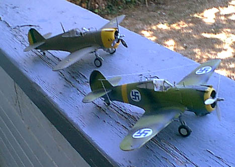
| Finnish
Hawk 75 |
Hawk
gallery |
| Kit |
Kit box |
Part # |
Engine |
Variants | Notes |
| P-36 Pearl Harbor Defender |
Twin Wasp |
USAAC, Brazil |
Reboxed by Academy |
||
| French Hawk 75 |
Twin Wasp |
Two French aircraft |
Same plastic as above |
||
| Curtiss Mohawk |
Cyclone |
One British, one Chineese, one
Peruvian |
ONLY a Mohawk IV. For I, II, or
III, use one of the other two kits above (French or Pearl Harbor.) |
||
| Hawk 75M/N/O |
Cyclone |
One Siam (Thai,) one (or two)
Chineese, two Argentinian |
Underwing cannon included, as
well as side window "blanks" and a different wing bottom. |
||
| Allied Hawk 75 |
Cyclone |
Dutch (NEI,) SAAF, Peru, China |
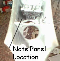 For starters, the
instructions would have you place the instrument panel far too far aft
in the cockpit, sticking out under a "T" shaped support frame. That
frame doesn't always exist in the real aircraft (it does in French
hawks, for instance - it's used to support some reflector sights) and
the instrument panel is under a coaming. Add to that the pain the panel
can be when trying to fit it into a fuselage half, and you see an
obvious problem.
For starters, the
instructions would have you place the instrument panel far too far aft
in the cockpit, sticking out under a "T" shaped support frame. That
frame doesn't always exist in the real aircraft (it does in French
hawks, for instance - it's used to support some reflector sights) and
the instrument panel is under a coaming. Add to that the pain the panel
can be when trying to fit it into a fuselage half, and you see an
obvious problem.| P-36 variants |
Wing guns | Which holes to open |
Engine |
Notes |
| P-36A |
None | None | Standard USAAC model. |
|
| XP-36B |
None | 1,100 HP R-1830-25 |
Engine testbed, converted P-36A
(38-20). Reconverted to P-36A. |
|
| P-36C |
Inner | Round hole (shell eject "bucket") | R-1830-17 |
38-85 testbed, 30 from last of
P-36A order built as P-36C |
| XP-36D |
Both | Rectangular holes | 174th P-36A converted (38-174)
with four .30 cal in wing. Later nose armament changed to two .50 cal. |
|
| XP-36E |
Both | Rectangular holes | 147th P-36A (38-147) with four
.30 cal MGs each wing. Nose .50 inoperable. |
|
| XP-36F |
Underwing cannon* | Round hole | 38-172. One 23mm Madsen cannon
under each wing. |
|
| P-36G** |
Both | Rectangular | Cyclone |
See note below |
| YP-37 (Hawk 75i) |
Allison inline |
13 built for service test |
||
| Hawk 75J |
Turbo-supercharged Twin Wasp |
Not built |
||
| Hawk 75K |
1200 Hp Twin Hornet |
Not Built |
||
| Hawk 75P |
Allison Inline |
XP-40 |
||
| Hawk 75R |
Standard engine |
Supercharger mounted under nose,
intercooler under trailing edge of the wing. Refitted with Cyclone, used
as demonstrator with NX-22028 markings |
||
| Hawk 75S / XP-42 |
P&W R-1830-31 (Twin Wasp) |
Fourth P-36A (38-4) for cowl
streamlining and (later) flying tail experiments, retained by Curtiss,
used by NACA. Washable camo used for 1939 War games. |
| Export model | Other names | Wing guns | Engine | User | Notes |
| 75A-1 | Mohawk 1 | Inner | Twin Wasp as P-36A | French, RAF |
|
| 75A-2 | Mohawk II | Both | Twin Wasp | French, RAF |
|
| 75A-3 | Mohawk III | Both | Improved Twin Wasp | French, RAF |
|
| 75A-4 | Mohawk IV | Both | Cyclone | French, RAF |
|
| A-5 | ? | Cyclone | China | One built | |
| A-6 |
Inner |
Twin Wasp |
Norway, Germany, Finland |
||
| A-7 |
Cyclone |
Netherlands East Indies |
|||
| A-8 |
All |
Cyclone |
Norway, USAAC, Peru |
ADF "Football," short wheel
pants. USAAC as P-36G. Ring/Bead sight, no internal gunsight |
|
| A-9 |
Mohawk |
Cyclone |
Iran (to Britain) |
Britain took over before
delivery to Iran. Sent to India as Mohawk. |
| Model |
Other name |
Wing Guns |
Engine |
Users |
Notes |
| Model 75H |
Hawk 75 |
Inner |
Cyclone |
Demonstrator (China, Argentina) |
Two built - Natural metal -
presented to Claire Chennault (NR-1726) . Argentina - NR-1276 - in
Argentinian markings. 300 lbs of bombs underwing. |
| Model 75M |
Inner |
Cyclone |
China |
112 made, production version of
75H - most destroyed in China |
|
| 75N |
Both |
Cyclone |
Siam (Thailand) |
||
| 75o |
Three per wing |
Cyclone |
Argentina |
30 shipped, 200 made under
license in 1940 |
|